Foundry & industrial processing Machinery EQUIPMENT & SYSTEMS
U.S. & Canada Call 1.800.457.5456
Model H-Series Electric Sand Heater
Home Products Sand Conditioning Model H-Series Electric Sand Heater Model H-Series Electric Sand Heater - Guide
Heating
This unit uses a SCR drive controller which monitors sand temperature and applies the exact amount of power required to all heating elements equally to achieve the desired sand temperature. This greatly extends element life by reducing temperature swings and overall operating temperatures. All elements are wired in one bank and run parallel. The SCR controller eliminates all electrical contactors and allows the H-Series to operate with no moving parts. Sand temperature with the H-Series are generally controlled within two degrees of set point.
Temperature Measurement
A critical part of heating is measuring the process temperature. In the H-Series, this is accomplished using a high tolerance Watlow Heating Control Processor and a type-J thermocouple. A second thermocouple is used to monitor sand temperature for over-temperature control. It is important to note that the tip of each thermocouple is directly exposed to the sand in the heater body. This ensures that the measured and controlled temperatures in the unit are actual, and not falsely averaged like other units that cover the thermocouple tip with a secondary iron thermo well to indicate constant temperature output.
Summer / Maintenance By-Pass Valve
The H-Series heaters come standard with a manually actuated butterfly valve that is used as a summer or maintenance bypass. Once the by-pass valve is opened there is no need for the fluidizing air to pass sand through the unit to convey sand. Energy savings are naturally assumed in the summer months and preventative maintenance functions can be performed without stopping production. A switch on the door of the primary electrical enclosure switches the unit from heat to by-pass mode electrically.
Fluidization
One of the principles of heating sand is the use of a fluidized bed to not only convey the sand through the unit, but also to force each grain of sand into contact with the heating elements. The H-Series uses as standard a compressed air system to fluidize the sand. Compressed air is introduced into the bottom of the heater body. The air is distributed into the body via an inexpensive canvas membrane sandwiched between two expanded metal screens for rigidity. This membrane allows fluidizing air to enter the body but prevents sand from falling into the air manifold system.
There are several benefits to fluidization. The first is sand temperature consistency. Since each grain is in constant motion on and around the heating elements, the sand temperature in the unit will be constant. This is absolutely critical for consistent temperature sand out of the unit.
A second advantage to fluidization is that fines can be removed from the sand just prior to it entering the sand mixer or mixing system. A standard component of the H-Series is a heavy-duty steel fabricated expansion chamber that allows grain size material to drop back into the unit from the exhaust air while allowing the fines to be pulled to the baghouse. This helps to reduce fines generated by sand transport and allows lower resin levels to be used.
Compressed Air Manifold

As a part of the standard unit, a full air manifold system is provided. This manifold includes a high efficiency bowl filter, Laman Brand dual stage cartridge filtering device, heavy-duty fluidization solenoid, air pressure regulator, and air pressure switch. The high efficiency air filtration system eliminates the saturation problems normally associated with fluidized bed membranes. The bowl filter and Laman Brand filter work together to eliminate 98.6% of water in the feeding air line reducing canvas replacement. The pressure regulator ensures that fluidized bed pressure is maintained constant. The air pressure switch is used as a safety device to shut down the heating circuit if there is insufficient air pressure to fluidize the sand, protecting the heating circuitry and elements.
Inlet Control Valve

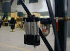
An important function in fluidized bed applications is maintaining a constant fluid bed depth. This aides not only in heating, but also fluidizing. One component required to accomplish this is an inlet control valve. This valve is used to shut off the supply of sand to the heater when the mixer is not calling for sand. The goal of this valve is to prevent packing the heater body. This valve eliminates problems with other systems that do not provide the valve as standard. These problems are inconsistent sand temperature, inconsistent fluidization, inconsistent sand flow, etc.

This valve also allows the continuation of fluidization after a heating cycle. This is important since the heating elements of the unit will have residual heat. If the sand is not fluidized after the cycle, the resonant heat in the elements will build up in the sand immediately around the elements. This not only causes inconsistent sand temperature, but also shortens element life. By shutting off the sand going into the unit, sand exiting the unit will also stop (a principle of the fluidized bed). The fluidizing air cancontinue to run without packing the heater body or overflowing the mixer inlet hopper or receiver.
Electrical Configuration

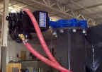
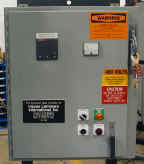
All electrical controls are housed in NEMA 12 dust tight enclosures. The primary electrical controls mount at floor level in most applications while the heater body is suspended above the mixer. The heater body has three primary electrical connection areas: the air valve enclosure, the power distribution enclosure, and the body top enclosure.
- The air valve enclosure houses the air solenoid valve used to trigger the air actuated inlet butterfly valve. It also contains the thermocouple termination points.
- The power distribution enclosure houses the three phase power connections going to the heating bundle.
- The body top enclosure houses the tips of the heating elements as well as the interconnecting wiring of those elements.
Mechanical Configuration

There are a few significant advantages of the H-Series over others. One is that the heating bundle used is designed into, installed, and wired as an integral part of the unit. Palmer does not use a purchased, drop-in industrial heating bundle like others. This allows for a single element to be easily replaced rather than waiting for the majority of the bundle to fail and replacing the entire heating bundle.
The H-Series also offers two ways to access the elements, either from the bottom (common) or the side. This makes element replacement and heater inspection much easier.
The heavy duty steel fabrication offers years of service resisting the abrasive action of the sand. The unit can be suspended by hanger bolts or directly bolted to top mounting rails provided to the bottom of structural I-beam or channel.
The large side access panel provides easy, quick access to the elements and fluidized bed membrane for inspection and maintenance.
Please Note: When any machine containing a sand control device (valve or slidegate) is installed, it is always a good idea to install a manual service valve in the supply pipe above the device. This allows maintenance service and inspections to be performed on the control device without requiring the silo/hopper to be empty.
Additional Palmer Products
Improve your productivity No-Bake Molding Equipment from Palmer.
Contact Us to learn more!
Call us at 1.800.457.5456 or fill out our simple form.
Copyright © 2025 Palmer Manufacturing & Supply, Inc. | Terms and Conditions | Privacy Policy


